Satake SWMC Moisture Control System
The Satake Moisture Control System SWMC is a reliable and cost effective way of controlling the addition of water to wheat during the tempering process. Using modular components, it is straightforward to install a fully integrated feedback control system in your own wheat mill.
The three main components of the system are:
1. The compact moisture sensing unit which is installed in a spout after the tempering machine
2. The Satake SWEC Water Addition Panel that receives the signals from the control panel and adjusts the percentage of water added
3. PC driven software Satake ‘MoistureONE’ with touch screen control panel normally located remotely in the mill control room

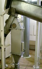
Moisture Sensing Unit
The Moisture Sensing Unit measures both the moisture content of the wheat and the temperature of the product. It is normally installed in a spout after the Tempering Mixer or SHD Hydrator, but can be positioned at any point either horizontally or vertically providing that it runs in full contact with the wheat.
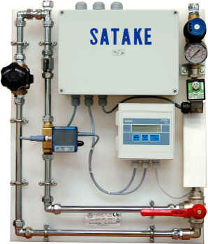
SWEC Water Control Panel
The Water Panel controls and monitors the flow rate of water using all electronic components. The control PC connects into the terminal box and sends the target flow rate to the SWEC. The SWEC returns the actual flow valve position to the PC.
Software Interface ‘MoistureOne’
Satake’s MoistureONE PC based control application allows the operator to manage all of the system functions from a single main screen. For easy operation in a potentially dusty environment, all main operations are set using the touch screen panel.
Common Function Settings
– Product Name Setting: The mill can assign a different product name to each wheat variety or grist that they mill.
– Product Target Moisture Percentage: The desired moisture value for the conditioned wheat in percent.
– Valve Start Position: The immediate position of the water valve on start-up. This allows for initial anomalies such as dry spots and unstable flow to be compensated.
– Maximum Water Valve Position: The maximum allowed position for the water valve as a percentage of full scale.
Recording
The common parameters and levels are displayed on the touch screen panel and also recorded on the PC’s hard disc for trend analysis and quality control purposes.
– Product Name
– Date, Time and Elapsed Time Since Product Start
– Target Moisture
– Actual Moisture
– Actual Temperature
– Water Valve Position